NOTE: this will be a discussion of fuel based tankless units. Electric units are available but due to the cost of electricity and the massive wiring issues involved with installing one I will not be addressing them here.
Tankless water heaters have been used for many years in other parts of the world but are only recently becoming a more common choice for US residential homes. As the name implies these devices provide hot water without storing it in a tank. They are more energy efficient than tank based heaters but there are some things to consider before installing one.
 |
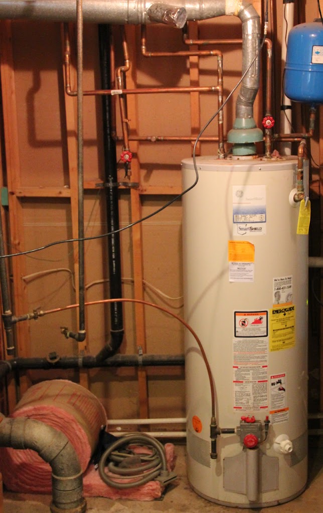
| Traditional 50 Gallon Natural Gas Water Heater |
Why tanks were used in the first place
Water has a very high specific heat. This means you need a lot of energy to make its temperature increase. As a comparison the amount of energy needed to raise the temperature of water 60 degrees would raise the temperature of the same weight of aluminum by 279 degrees. This makes water an excellent coolant but also very difficult to make ready for use in showers and dishwashers.
So the tank based water heater was created. These devices store a large amounts of water and heat it up over time. Since you don’t have to heat the water all at once you can use a more modest electric heater or gas burner.
When water is needed you use some from the heated tank. The tank is constantly supplied new cold water to replace the hot water used which is then slowly heated for use.
Tanks have two major issues
First. The tank based water heater cannot heat its supply of water as fast as it will be used in the building. This is why it has the tank, to supply a buffer of hot water so it has time to heat up more. If the usage in the building exceeds the buffer (the water in the tank) then your hot water supply temperature will decrease as the new cold water entering the tank, to replace the hot water used, has not had time to be heated. Most tank based water heaters are rated by there capacity in gallons (the buffer size) and their recovery time (how long it takes to get the buffer back up to temperature).
Second. When you are not using any hot water the tank sits idle. This doesn’t seem like an issue but it is a big energy inefficiency with tank based water heaters. Any time you have something hot sitting in a cool room the heat from the hot object will diffuse into the surrounding room until both are the same temperature. This means the hot water in the tank is constantly loosing its heat to its surroundings (assuming they are cooler) over time. Once the temperature of the water in the tank falls to a certain point its heater will fire to heat it back up. The energy needed to keep the water in the tank warm when no hot water is being used is called stand-by loss.
Manufactures of tank based water heaters try to minimize stand-by losses by slowing the rate at which heat escapes the tank. This is normally done by insulating the tank. This is also why older tanks can benefit from having an insulating ‘blanket’ placed around them.
Why tankless units are more efficient and awesome
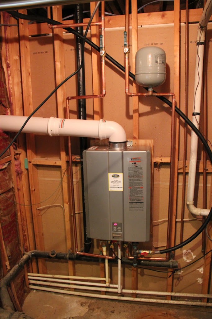
 |
| Tankless Water Heater |
Since tankless heaters have no tank, they have no stand-by losses.
In addition tankless units can be built with high efficiency heat exchangers which extract more energy from the burning fuel and place it into the water instead of exhausting it to the atmosphere as hot gas. Some high efficiency units have exhaust gas temperature of less than 120F (this leads to condensate issues discussed later).
Since the water is heated in real time the tankless unit can provide hot water so long as you have water to heat and fuel to burn. Tankless systems are rated by the temperature rise they can sustain at a given flow rate. An example might be +40F at 9.3 gallons/minute.
Many tankless systems use electronics to monitor the flow of hot water out of the system. These same electronic may also be used to detect slow leaks in the hot water system. Once detected the system displays an error and shuts a computer controlled valve stopping all hot water flow.
The components of a tankless water heater are serviceable and replaceable. Generally only the burner of a tank based system is ever replaced. Replacement parts for tankless systems include the heat exchangers, electronics and various valve assemblies.
There are some downsides
Since the water is heated in real time the unit will need a lot of fuel. This fuel will be used very efficiently and only when needed but it is still quite a lot. A three or four bathroom house might use a 50 gallon tank based water heater with a heater rated at 40kBTU or a tankless rated at 200kBTU. Because of this need for great quantities of fuel a tankless unit may require larger fuel lines not available where an old tank unit was located.
Many tankless models use electronics to provide very tight control on the temperature of the out going water. This means you will need a standard electrical outlet in close proximity to the new unit whereas most tank models have no such requirement.
Going tankless will involve a good bit of labor. Tanks rest on the floor and have their water inlet, water outlet, and temperature and pressure relief valves on the top while tankless units attach to the wall and have their water inlet, water outlet, and T&P relief valve on the bottom. So you can expect a fair bit of water line rerouting to get a tankless to take the place of a tank unit.
High efficiency models will produce condensate. In low efficiency heaters combustion waste products ride the hot exhaust gas leaving the unit and exit to the atmosphere. More efficient units produce exhaust gas at a temperature so low some of the combustion products will condense (like dew) and drain from the unit. This condensate is corrosive and local codes will dictate what may be done with it but at the very minimum you likely need more more piping to deal with it.
The bottom line
In my case the tankless unit cost $1150 and comes with a 12 year warranty on its heat exchanger. A comparable tank system would run about $600. At the current price of natural gas in my region the unit will save around $1000 in fuel cost over its warranted lifetime. This more than compensates for the up front cost of the unit but we have not yet considered installation costs.
My unit was installed for $1400. Other vendors in the area quoted as much as $2900. This does not include the cost of the unit just the cost to install it. In my case all of the prerequisites were met such as proximity to an exterior wall, gas supply, and an electrical connection. Even so the tankless unit could not make use of the existing flue duct nor the condensate lines from the AC units which already ran though the exterior wall (both of these restrictions are mentioned in the owners manual for the unit). So even in near ideal conditions there is likely to be a lot of work if you are replacing an old tank unit. Installation took a single technician about 7 hours to complete.
Despite the various advantages of a tankless water heater the economics of installing one may prove to be complicated when all costs are factored. Even if it proves to be a money saving decision it will likely be a long term savings.