In short:
Can you: Yes.
Should you: No.
In short:
Can you: Yes.
Should you: No.
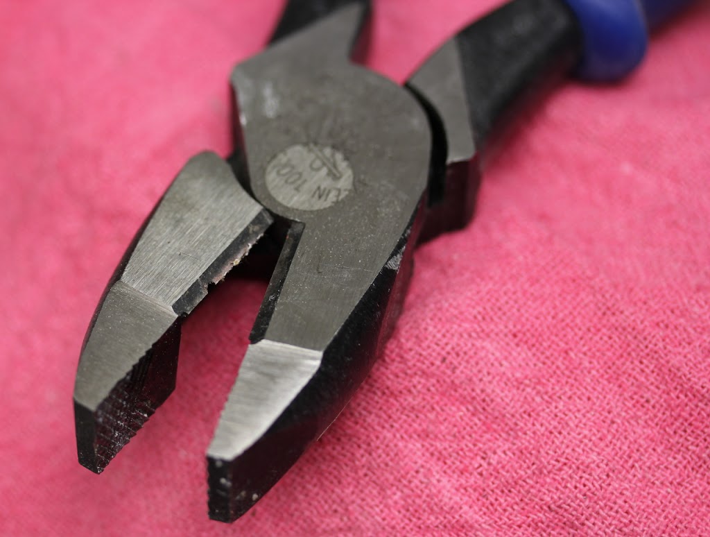 |
| my injured lineman’s tool |
So I was working in the garage installing new lights. I had verified the circuit breaker responsible for powering the circuit I would be wiring the new lights into, no problems here. Before I got around to installing the lights I realized I had other work to take care of first. So I turned the breaker back on as it was also powering outlets I needed, no problems here either.
After I was done with the sidetracking work I turned the breaker back off in preparation for wiring the lights up, no problems here either. Using my lineman’s tool I then cut the Romex line I would be reworking to run my new lights… problems.
Immediately I had lights, not of the useful overhead lighting kind, along with the popping and hissing noises which accompany shorting a live wire. I was also working on a ladder, which in this case functioned as an unnecessary excitement multiplier, which I ungracefully abandoned. The wire was roasted and my tool now had a notch of metal blasted out by the short circuit arc.
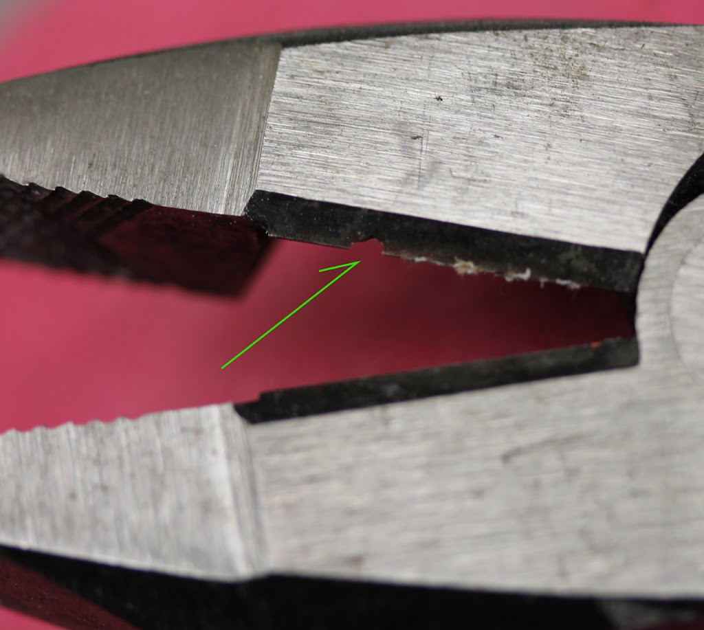 |
| closeup showing missing metal |
But the circuit breaker was off. Why was there still power?
Simple. I had turned off the wrong circuit breaker. The breaker I shut off did not have any visual manifestations which would indicate I had gotten the wrong one. So I proceeded with my work. The error was not verifying the power was off at the place and time of the work. Had I checked the line right before starting work again (I had several tools which would do this for me) I would have caught the problem.
Instead I am down one pair of pliers. A small price considering other possible outcomes.
This combination headphone/microphone line has a break in its outer casing.
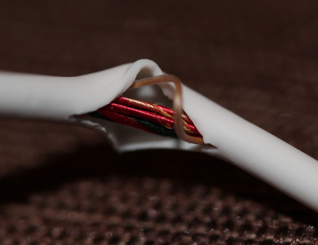 |
| The broken casing |
This causes the wire the catch on things. While the electrical connections are still good this condition is an inconvenience and needed to be repaired.
Heat shrink tubing is perfect for this issue, expect I did not have a size of tubing on hand which would fit over the end connections of this wire and shrink down to a size necessary to grip the line.
The line could be cut and the tubing slid over it but this would entail reconnecting 4 electric lines and that is just a hassle.
I opted to use a larger diameter tubing and the build up the area to be covered with electrical tape. The tape alone would not be the best solution for this issue as unprotected it is likely to unravel.
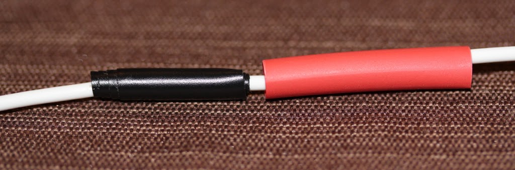 |
| Line prior to shrinking |
After the line was taped the tubing was placed and heated. Ideally I would have used white tubing to match the line but this was all I could find without the trouble of ordering more.
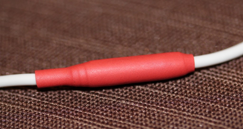 |
| The finished line |
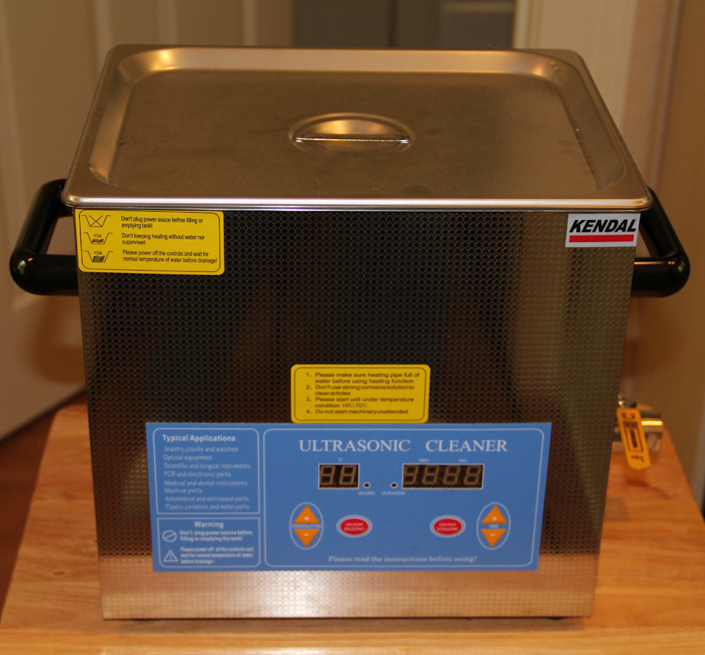 |
| an ultrasonic cleaner |
Ultrasonic cleaners function by bombarding items with sound whose frequency is beyond the range of human hearing. A discussion of the specific mechanism of cleaning is complex and beyond the intent of this post. What follows are some pointers when using a simple ultrasonic cleaner.
Ultrasonic cleaners will impart their cleaning action to the objects submerged (normally in water) inside them. As such you will only be able to effectively clean items which will fit inside the cleaner. Items with unusual aspect ratios (such as rifle barrels) will likely require a more specialized unit as their shape will not be as common.
Some units will also have heaters for heating the cleaning solution. This is an excellent feature and greatly accelerates the cleaning process. The unit pictured at the top of this page will heat the cleaning solution to about 176F (80C). For comparison most residential water heaters will heat your hot water supply to 120-140F. If you use the heating function some of the cleaning solution may evaporate from the unit and condense on the inside of the lid. Thus care should be taken when removing the lid especially if the condensate may contain corrosives (more on this later).
Cleaners will generally come with some type of wire basket for adding and removing items without getting your hands in the cleaning solution. In addition larger units will have a drain valve for emptying the cleaning solution when it becomes fouled or unusable.
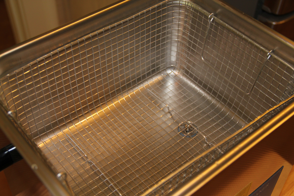 |
| cleaner interior |
Simply place the items inside the cleaner, then turn it on or set the timer. The unit does not need supervision. Certain types of items are more easily cleaned in these cleaners than by other methods. Objects having intricate shape or edges cleaning brushes could get caught on are good candidates for ultrasonic cleaning.
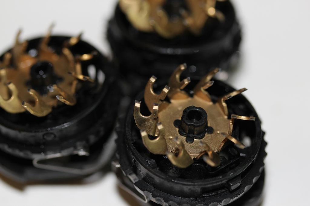 |
| electric razor blade assemblies are easily cleaned in an ultrasonic cleaner |
Often cleaning will be more effective if some type of solvent is added to the water to form a more effective cleaning solution. What you can use in your cleaner will depend on what it was designed for. Most cleaners can be used with household detergents.
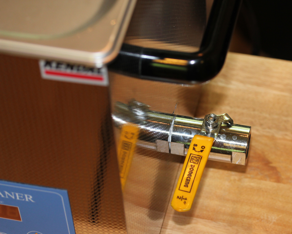 |
| cleaner drain valve |
More corrosive/awesome cleaners like sodium hydroxide should only be used if the unit is intended for use with them. Even if your cleaner is constructed of a metal body resistant to attack by corrosives (like stainless steel) other components, like the drain valve seals, may not be. In addition a single successful use of a cleaner with a powerful solvent does not indicate the unit is not suffering damage. While not immediately destroying the unit some substances may greatly reduce its working lifespan.
Ultrasonic cleaners come in a variety of sizes and prices. The one picture in the article runs about $400. Other smaller units can be less expensive but may not come with a heating function.

NOTE: this will generally pertain to C# but applies to any programming language which uses similar exception handling (for example Java). This article covers a few misconceptions about exceptions and is not intended as a complete reference. In depth study of this important programming aspect is highly recommended.
public static bool TryParse(string s, out int result)
This method does not throw a FormatException. Instead if will return a boolean indicating if the conversion was successful and if so it will provide the converted value via the result out parameter. By using a boolean instead of an exception this call avoids the cost associated with handling an exception.
Does this method keep its contract with its user? Yes it does.
Whereas the Parse method implies by its signature it will return a converted value TryParse implies it will attempt a conversion. This distinction in naming is important in creating an API your users will be able to easily understand.
A simple look through the FCL will demonstrate the occurrence of TryX is very limited. While the TryX methods seem to match the X method in capacity and excel it in speed it fails in code simplicity. The code necessary to support the TryX method is more cumbersome than the a simple X method.
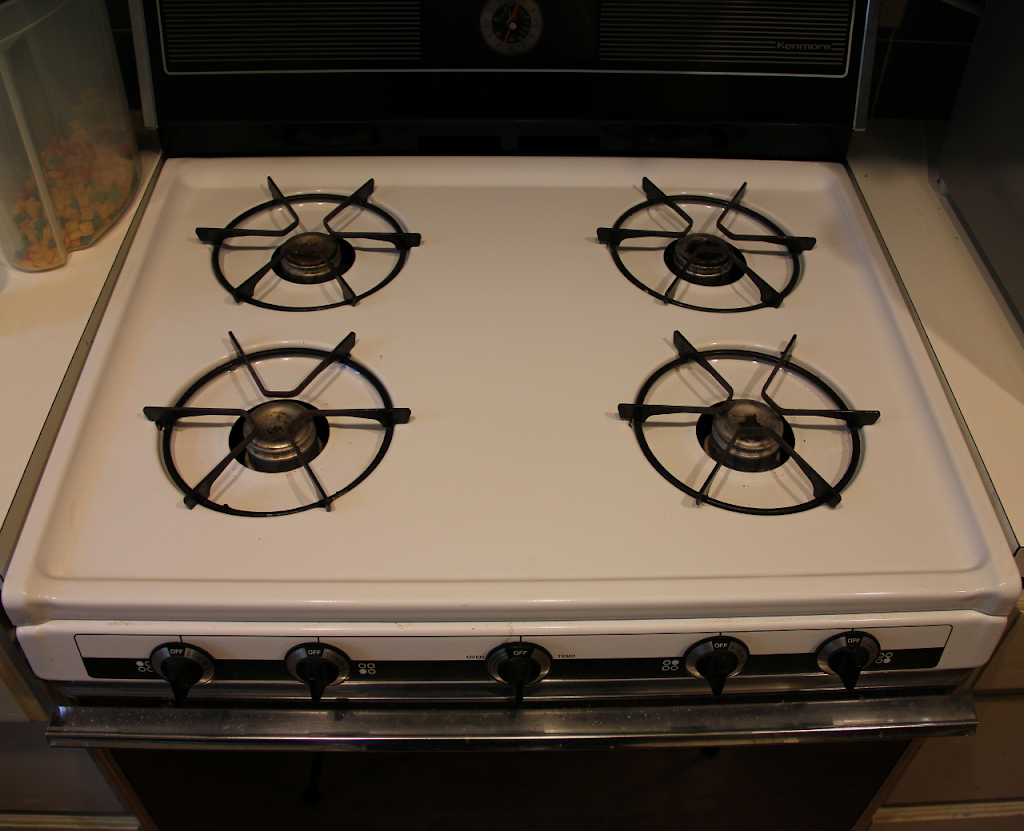 |
| The patient needing attention |
The above is my stove. It is an old stove. I think I have used this stove once in five years. I don’t really care much about the stove. Unfortunately someone recently pointed out to me the burners on the stove do not light correctly. So in accordance with my ‘fix ALL the things’ policy it was torn apart until fixed or destroyed, whichever came first. Mercifully this ended in a fixing and what follows is what I discovered.
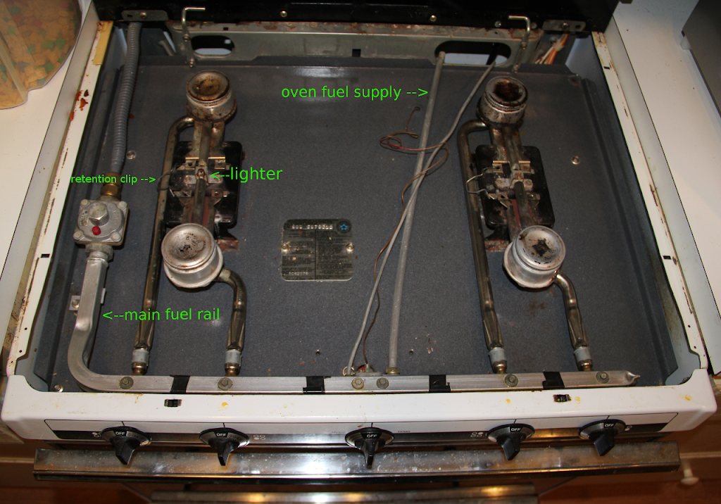 |
| stove with the top removed |
Opening the top of this stove is as simple as lifting the top from the front. Once raised the top can be slide off of its hinges exposing the amazingly primitive bits underneath. The gas line comes in from the upper left and travels down the left side to (what I think is) a regulator, a flame arrester, or both. This gas line then takes a 90 degree bend and forms the main fuel rail at the front of the stove.
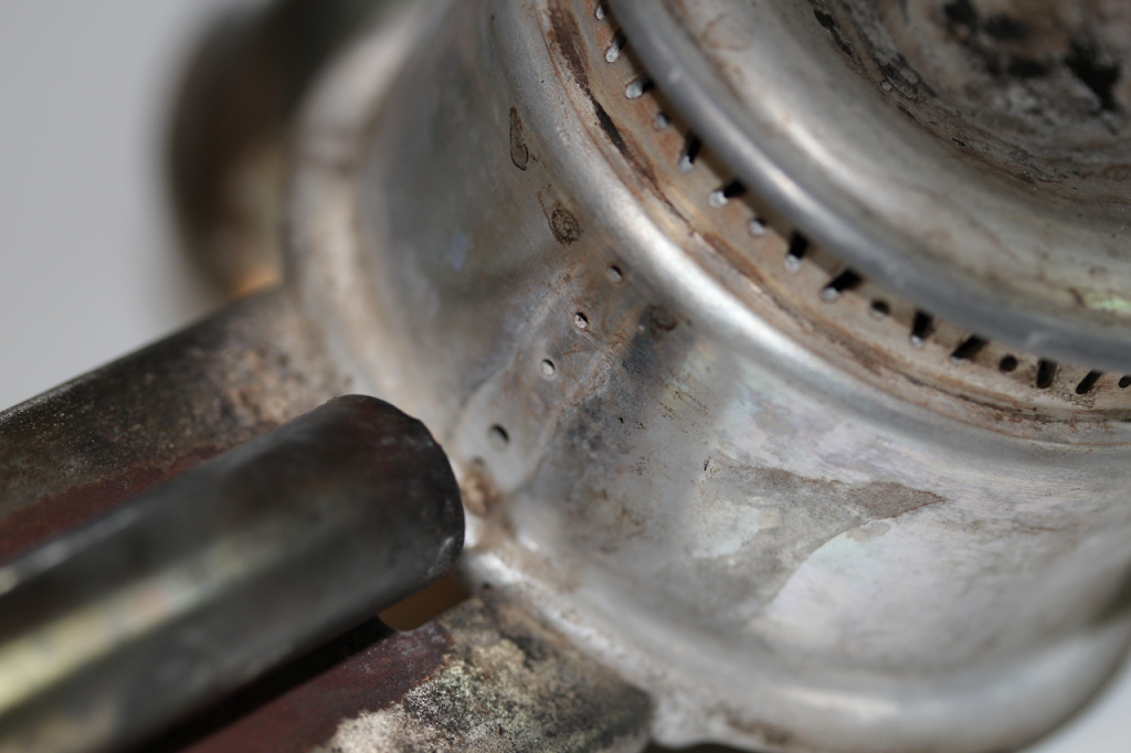 |
| closeup of the ignition flame ports |
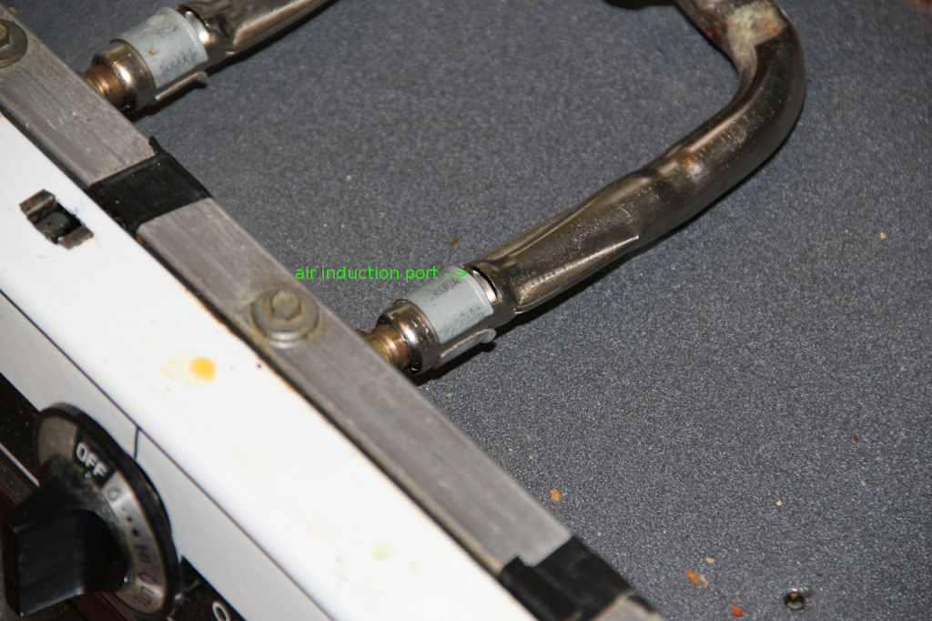 |
| air induction port |
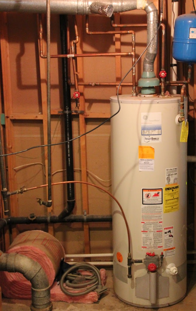 |
| Traditional 50 Gallon Natural Gas Water Heater |
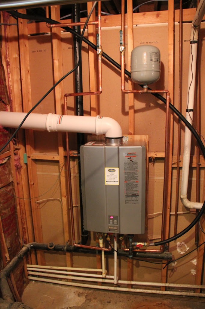 |
| Tankless Water Heater |
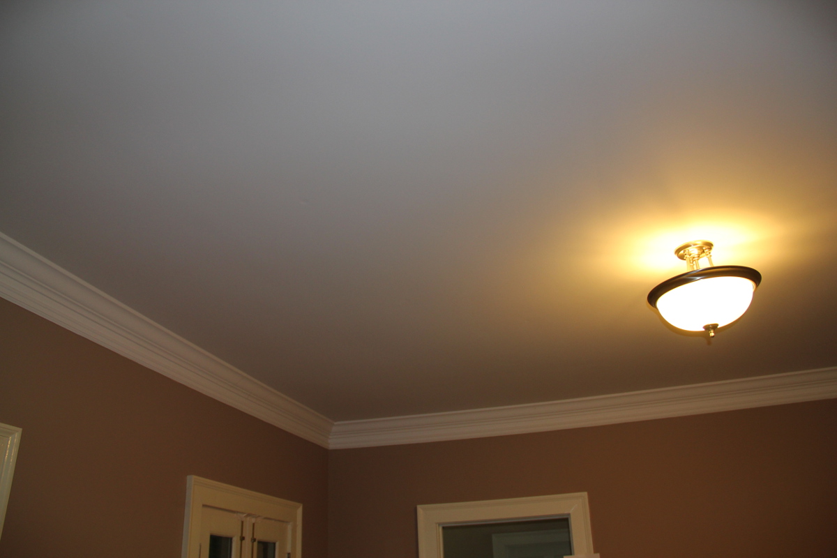 |
| A drywall ceiling |
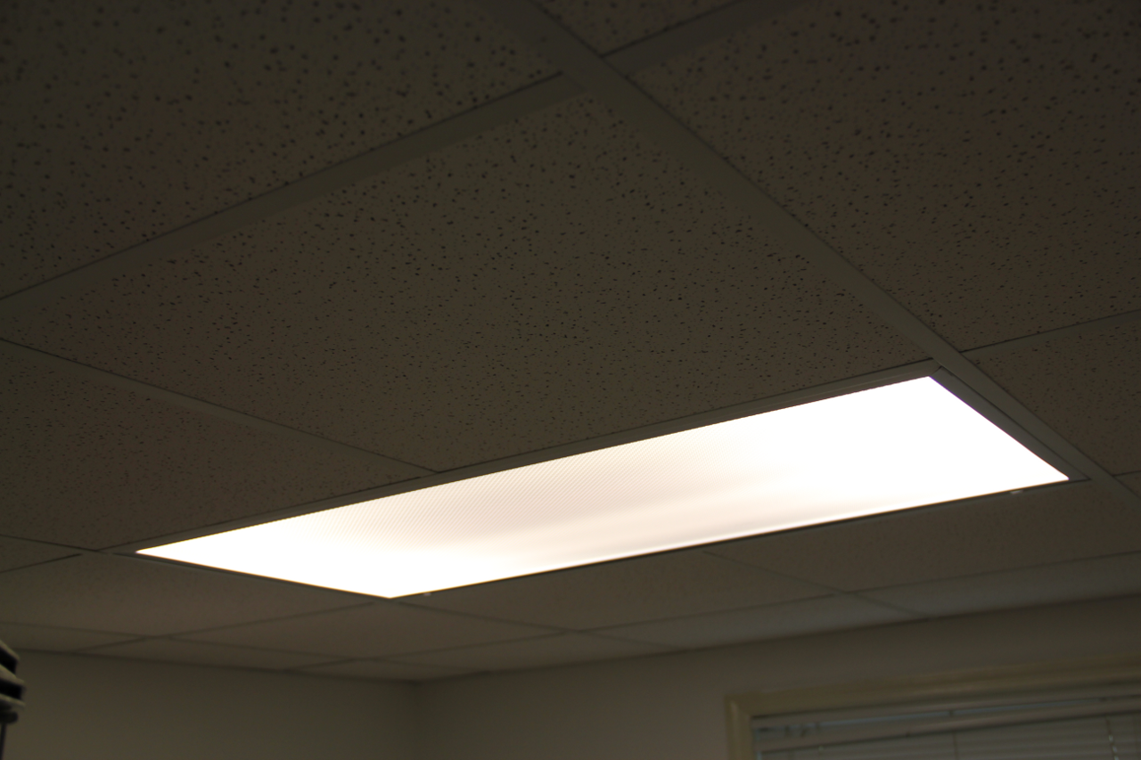 |
| Traditional suspended ceiling |
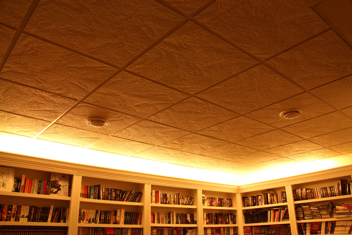 |
| Awesomeness++ suspended ceiling |
 |
| Suspended ceiling with can lights |
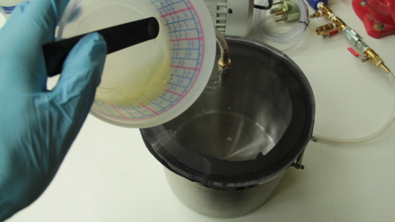
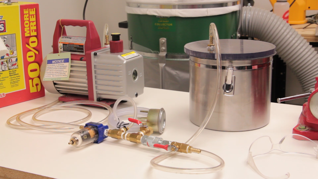
People who saw the vacuum chamber video were disappointing I did not actually use the chamber in the video. This should correct that issue. Here I am using my vacuum chamber to degas a small amount of West System epoxy.